
Article
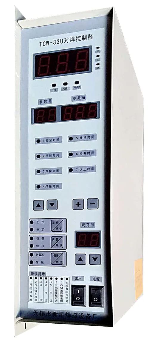
Iron ring copper ring pneumatic butt welding machineIt is a complex and intelligent machine designed for welding metal circles,D-rings, triangle frames, etc.Resistance butt welding machine, the model of NOVEL WELDER is UNQ. Generally, there is no need to look at the wiring method of the controller. Only read this if you accidentally crash or burn out the controller, then purchase the controller and install it yourself. There are quite a few things to pay attention to, so please read carefully!
1. Description of wiring board terminals:
Terminal number
Terminal name
How to use and function instructions
Sampling signal input during constant current control
No. 1 and No. 2 are the signal input terminals of the transformer;
1. No. 14 is the signal input terminal of the induction coil.
Current transformer signal cannot be accessedNo. 14! Otherwise the controller will be burned!
Triac trigger terminal
No. 3 and No. 4 are a set of triggers, No. 3 is connected to the cathode of a thyristor, and No. 4 is connected to the emitter;
No. 5 and No. 6 are a set of triggers, No. 5 is connected to another thyristor cathode, and No. 6 is connected to the emitter.
3, 4, 5, and 6 cannot be picked incorrectly! Wrong connection may burn the controller and thyristor!
Controller power supply
Nos. 7 and 8 are the power input terminals of the controller.
If there is no current output during operation and appears“Er02”, make sure that terminals 3, 4, 5, and 6 are not connected incorrectly, please swap wires 7 and 8.
Start and thermal protection input
No. 9 and No. 10 are the No. 1 start signal inputs, and the current specifications are executed when starting;
No. 9 and No. 19 are the No. 2 start signal inputs. When starting, the last specification, namely No. 9 specification, is fixed;
No. 9 and No. 16 are thermal protection device signal inputs
1. If the external thermal protection device is a normally open contact, please set "AA" to "00"
2. If the external thermal protection device is a normally closed contact, please set "AA" to "01"
3. If the "AA" setting is wrong, it will prompt "Er03”
Air valve output
Nos. 11 and 17 are the output terminals of the main air valve (24V)
Nos. 12 and 17 are the output ends of the upsetting valve (24V)
13. No. 17 is the auxiliary air valve output end (24V)
The common terminal of each valve isTerminal 17 +24V
1. The maximum power of a single air valve shall not be greater than 3.6W, and the total output power of the three groups shall not be greater than 10W.
2. If the power of a single air valve exceeds 3.6W or the rated voltage of the air valve is not 24V, please connect an external power supply and a 24V intermediate relay.
3. When Ab=01, terminals 13 and 17 are fault action outputs.
4. When there is no auxiliary air valve, No. 13 and No. 17 can be used as the welding end signal output, which may be used in the welding production line.
24V power output
The 17th is + and the 18th is -
Maximum power + power of each valve≤10W
Note:1. Please do not change the wiring at will! If there is no current output and Er02 appears during operation, please swap wires 7 and 8 of the power supply after making sure that 3, 4, 5, and 6 are not connected incorrectly.